Section 13.1 Setup
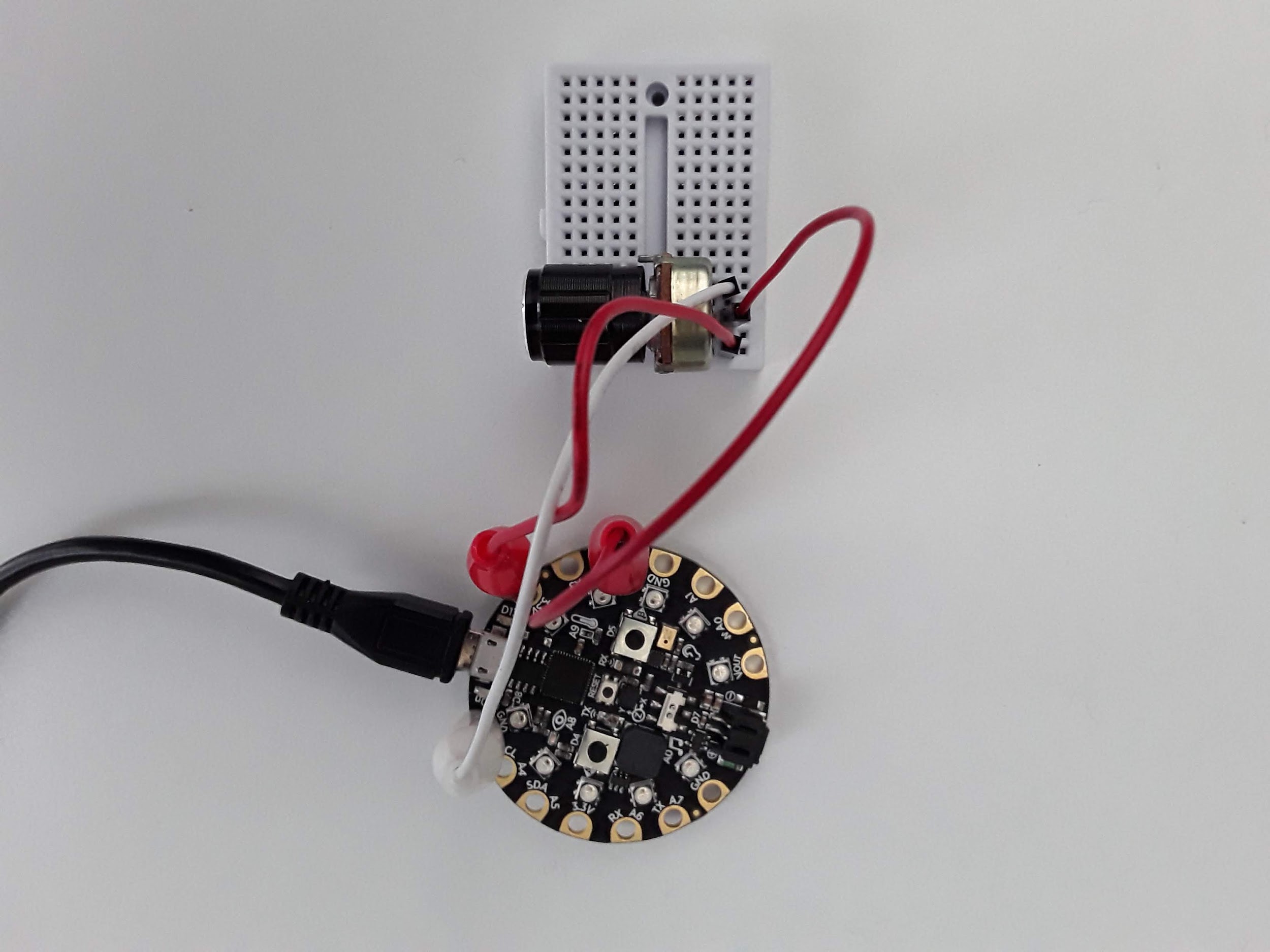
Here’s my circuit all hooked up without a resistor in series. Two legs are connected to 3.3V and GND while the middle leg of the potentiometer is connected to pin A2.
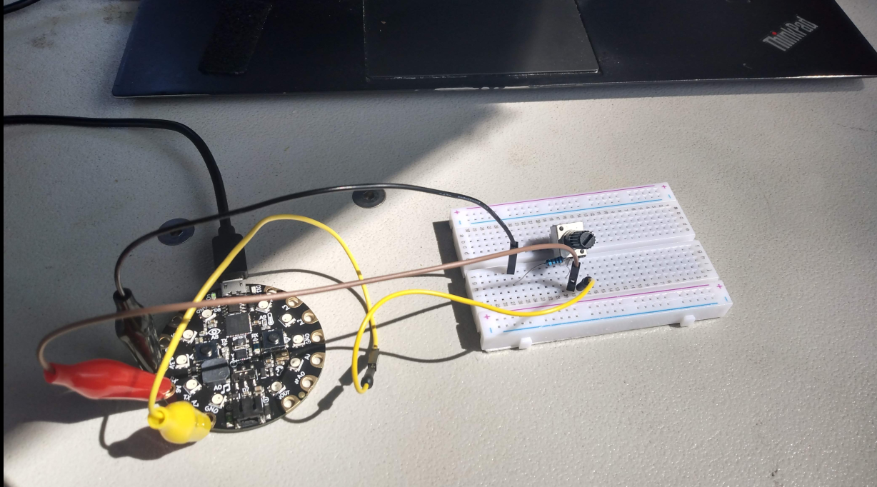
As I said before, some potentiometers do not have enough resistance when turned all the way down. I suggest that you put a resistor in between the third leg and ground. Some experimenters have melted plastic or gotten really hot. One student even blew up a potentiometer. Here is my circuit with a resistor in series.
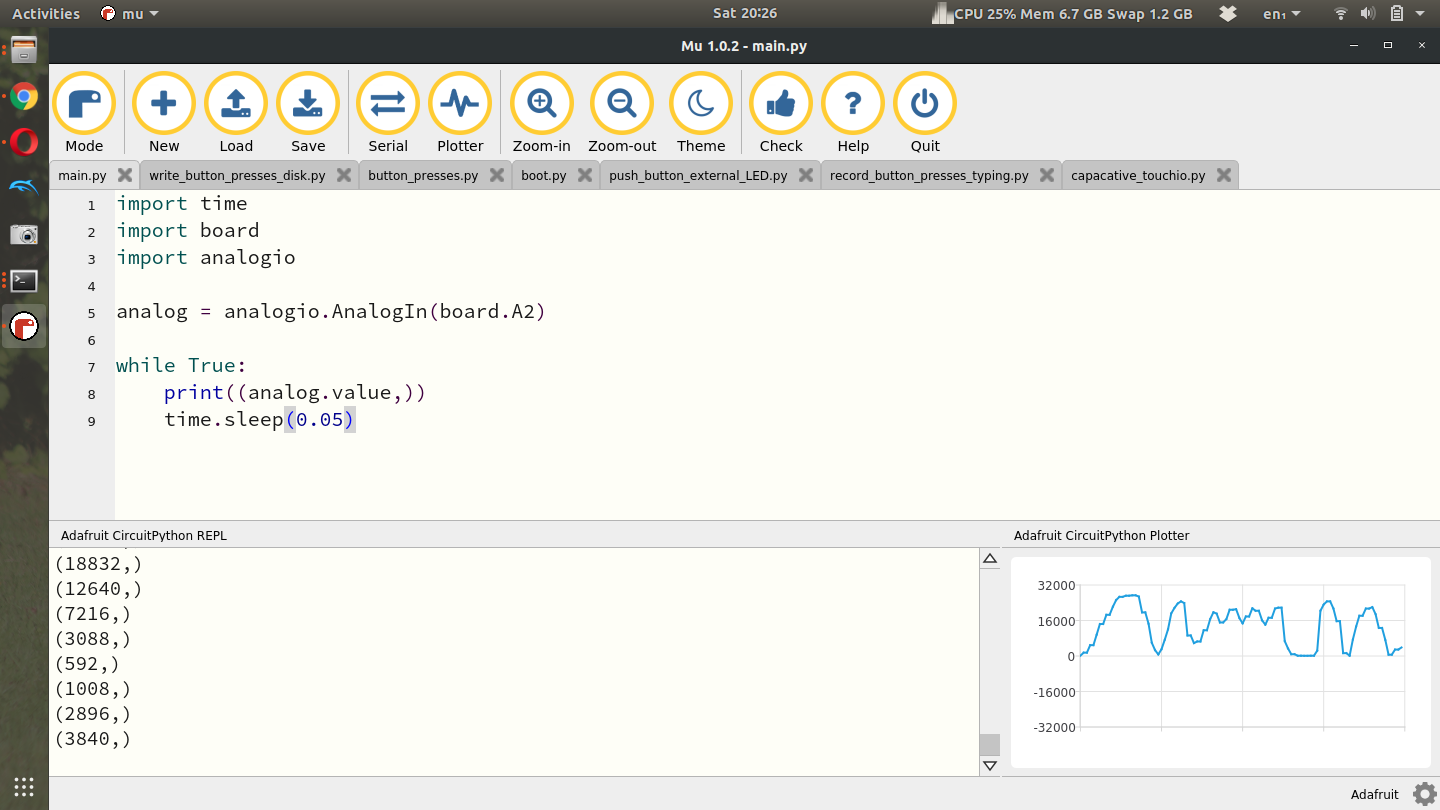
There is a relevant Adafruit Learn Tutorial to help with the analogio module but I’ll explain the minimum required here to get some analog values plotted in Plotter and on your computer[32]. First let’s take a look at some simple example code to read an analog signal and plot it using the Plotter[33].
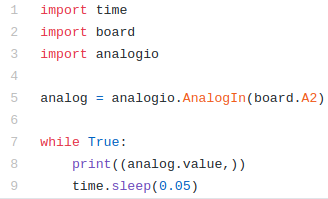
In the example code above, lines 1-3 again import the necessary modules with analogio being the new module here. Line 5 creates the analog object by attaching pin A2 to the analog function. Lines 7-9 then simple read the analog value and print it to Serial and the Plotter. Running this code on my laptop and turning the knob on the potentiometer produces this output. My potentiometer has a very large knob on the front and is easy to turn. Some potentiometers have a small screw on top that you need to turn with a screwdriver. Turning the screw or the knob results in chaning the resistance and therefore changing the voltage read by the CPX.
For this lab I want you to spin the potentiometer all the way to one side and then the other while recording time and the analog value. I then want you to plot the data with time on the x-axis and voltage on the y-axis. Remember to convert a digital output to voltage you just need to use the equation below where D is the raw value from the analog port. 3.3V is the range of the ADC and \(2^{16}\) is the maximum value the ADC can represent.
\begin{equation}
V = \frac{3.3D}{2^{16}}\tag{13.1.1}
\end{equation}
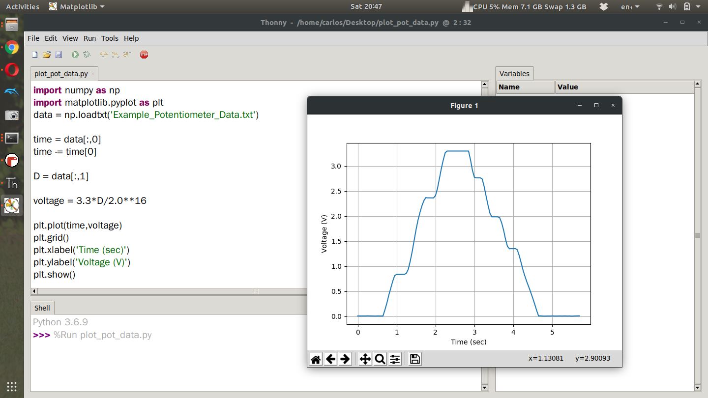
After doing this experiment myself, this is the plot I obtain. The code is not provided as reading data and plotting has been discussed in a previous lab (See Chapter 9). From the screenshot though you can see how I convert the digital output to an analog signal.
NOTE THAT ON LINE 6 IT READS
time -= time[0]
Notice the minus sign in front of the equal sign. That effects a lot.