Chapter 8 External LEDs and Push Buttons
In this project we’re going to use the same blink code as Chapter Chapter 6 but modify it to blink an external LED. Another goal of this lab is to familiarize yourself with some of the pins on the CPX and create a simple circuit using the 5V (VOUT) pin on the CPX and one of the Analog pins.
Your laptop has a battery with something between 10 to 20V. There are DC to DC converters in your laptop that provide 5V to your USB ports. These USB ports can be used to power your CPX as you have done in the past few labs.
If you purchased the optional battery pack you can also power the CPX using 3 AA batteries [34]. These batteries nominally have 1.5 V but fully charged it’s actually something like 1.8 V. So 1.8 times 3 is 5.4V which is enough to power the CPX. If you have the battery pack and some AA batteries, give it a try. If you still have the blink code from the last project on board you’ll see the D13 LED blink as before. You won’t be able to see the serial print() output as before but that code will be running which is why D13 is blinking. I have noticed that some of the battery packs have power and ground wires swapped. If the battery pack doesn’t work it may be because those two wires are backwards.
The CPX itself uses 3.3V logic which means when it converts numbers to binary a 0 (False) represents 0 volts and a 1 (True) represents 3.3V. The CPX has ports that are labeled various things. GND stands for ground and you need to hook the negative end of your circuit to this and it also has VOUT which supplies 5V to any circuit you build. Hook the positive end of your circuit to the VOUT pin. There is also a port labeled 3.3V and obviously that outputs 3.3V. The Figure below shows an Arduino Metro hooked up to an LED on a breadboard (Courtesy of Tony Dicola [37]).
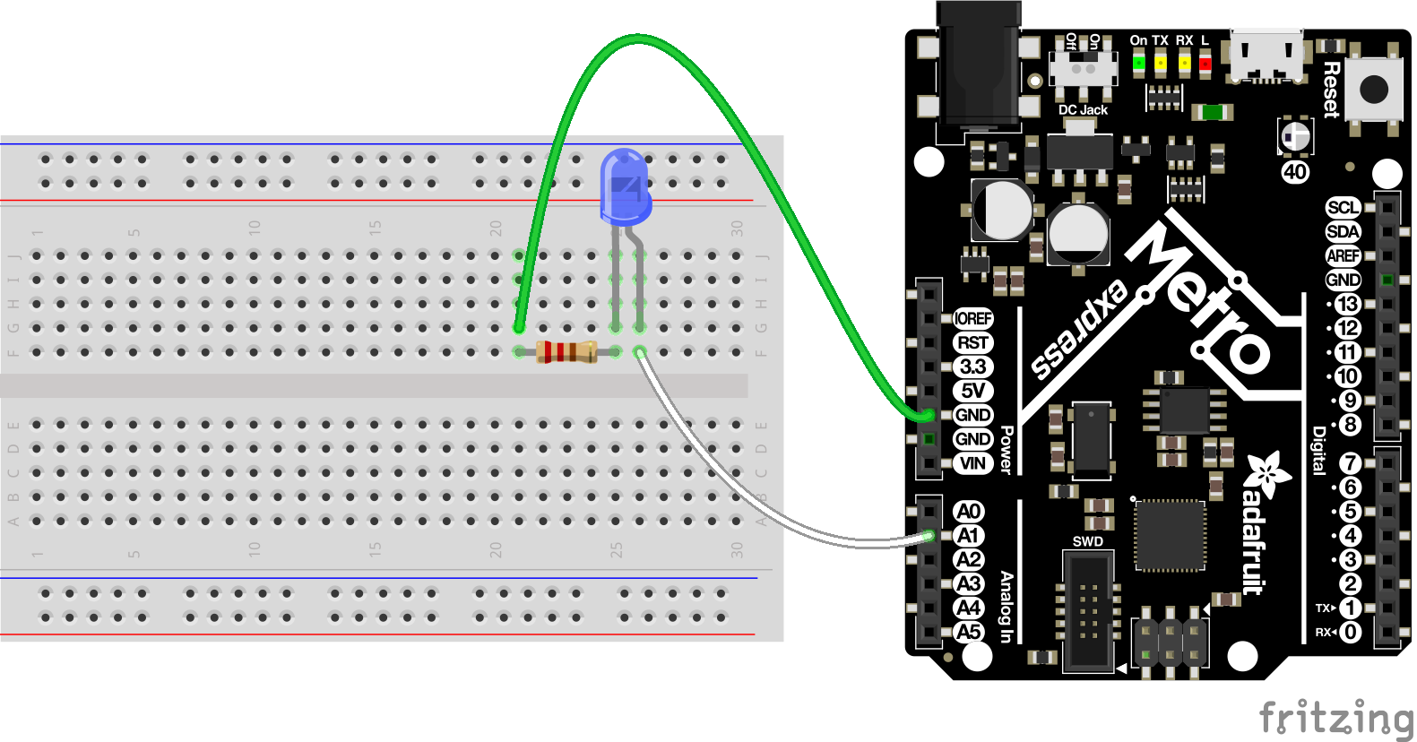
Your lab today specifically involves an external LED as shown above. You can read about LEDs more online if you wish[59]. Remember that the long leg of the LED is the positive end and the short leg is the negative end. The task today is to wire an LED up to the CPX in multiple ways. The figure above shows the LED connected to the A1 pin but we will be wiring up the LED to multiple pins on the CPX/CPB to gain understanding in how the circuit works. Note, whenever you modify a circuit on the breadboard, always be sure to remove power from the CPX. You can damage multiple components if you’re not careful.
