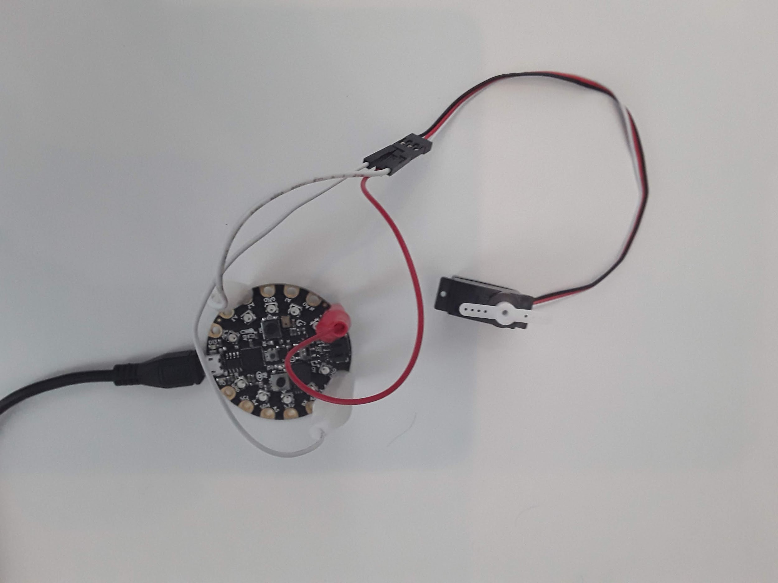
To start, make sure you follow the wiring diagram in the introduction and wire up your servo to the CPX/CPB. In my circuit I just picked pin A2 since I’ve been using it so much in the past. Very important: It is recommended to power a servo through an external power supply instead of the CPX. Servos can draw a lot of current and the CPX although it supports 5V can only provide so much power (P). Remember that P = VI so if P is low it means current is low. If the servo pulls more current than the CPX can provide the CPX will “brown out” which means it will go into a safe-mode setting. If you have the AA power supply you may consider doing that. For small servos you hopefully won’t have any issues. However, on the off chance your servo does put you into safe mode I recommend making small movements in your code to drive your servo. For example, if moving the servo directly from 0 to 180 puts your system into safe mode, try moving from 0 to 45 degrees instead.
Figure19.1.1.Photo of a servo connected to a CircuitPlayground Express
As I said before, a servo takes in a square wave. The square wave has a duty cycle in units of microseconds. If you send a roughly 500 us square wave to a servo it will rotate all the way to the left. If you send a roughly 2500 us signal to the servo, it will turn all the way to the right. The code to send PWM signals has been thoroughly explained in the Adafruit Learn system[32]. I also have a simple servo.py script on Github[33].
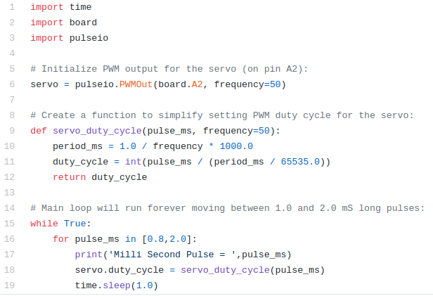
In this code as usual the top 3 lines are used to import the necessary modules. The pulseio module is used here to create a servo object on line 6 by connecting to pin A2. Make sure to change the pin to whatever pin you have the signal wire hooked up to. Lines 9-12 create a function that pulse in milliseconds and compute the duty cycle of PWM signal. Lines 16-19 then kick off an infinite while loop where a 800 us signal is sent to the servo and then a 2000 us signal is sent using a for loop which starts on line 16. You’ll see servo command on line 18 which is responsible for sending the microsecond signal to the servo. The function servo_duty_cycle converts the pulse in milliseconds to a duty cycle. The value is then passed to the attribute of the servo object servo.duty_cycle. If you put this code on the CPX and run the code you will hopefully see your servo turning left and right in 1 second intervals.
Besides making the servo move back and forth I’d like you to vary the pulses on line 16 SLOWLY until the servo can’t move any farther. This line of code is a for loop which loops through the array currently showing [0.8,2.0]. If you change that array to [0.9,1.2,1.5,1.8] the servo will move to a pulse in milliseconds of 0.9, 1.2, 1.5 and then 1.8. The for loop is a great way to loop through multiple commands. Using this array, determine the minimum pulse you can send to the servo and the maximum pulse you can send to the servo. If the servo makes a funny noise it means you sent a signal outside the bounds so try a different signal. Hence the need for moving the pulse signal slowly. If you change the array to just 1 number [0.8] the servo will just move to 1 angle and stay there forever. NOTE THAT IN CIRCUITPYTHON VERSION 7.0.0 YOU HAVE TO USE THE PWMIO LIBRARY INSTEAD OF THE PULSEIO LIBRARY.