Section 9.4 Method 3 - Logging Data Directly to on board memory
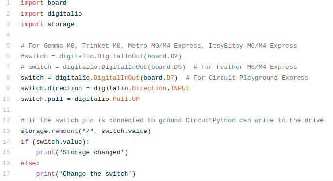
The problem with the above 2 methods is that you need a laptop to log data in the field. It would be nice if you could use the optional battery pack and just have the CPX log data on the CPX itself. This is the most complex way but in my opinion the best way. In order to get this to work you need to allow the drive on the CPX to have read/write permissions. This requires you to load a piece of software called boot.py and put it on the CPX. I have this software on my Github[33]. The software is shown below. The first 10 lines are probably very familiar. Import some modules and then create a switch object. Line 13 is where all of the storage permissions are changed. If the flip is switched towards the A button, the storage module is used to allow you to write to the CPX. The problem here is that if you do this, you won’t be able to edit code. I’ll explain the procedure here in a minute. As always, the relevant Adafruit tutorial is on the Adafruit Learn System[32] if you want to read more about it. Again make sure you store this file onto the CIRCUITPY drive and save it as boot.py
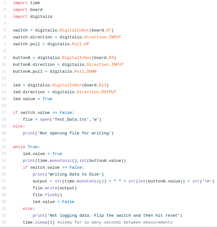
In addition to storing the file boot.py you’ll need to edit your main.py script to only log data when the switch is moved towards the B button. The software to record button presses on disk is shown below and as always on my Github[33]. In this software we again see the standard commands. Lines 1-3 import all the modules we need and then 5-15 create a switch, a button and an LED. In this case we’re using the LED soldered to the board. Line 17-20 check to see if the user has flipped the switch. If the switch is False the storage module on boot.py will allow the drive to act like a data logger and it will open a file called Test_Data.txt for writing (“w”). If the switch is True then the user will be notified that the file has not been opened for writing. Lines 22 through 33 include the infinite while loop. Line 23 turns the LED on and line 24 prints out the current time and the button value in integer form. If the switch value is False the program will create an output string by converting all numbers to strings using the str function. Notice that there is a str(“\textbackslash n”) at the end of the output variable which tells the computer to write a new line of data to the file. Lines 28 and 29 write the output to the file from line 18 and then flush the output which means the CPX waits for the data to be fully written before moving on. It also turns the LED off so we know the CPX took data even when we aren’t looking at the Serial monitor. If the switch value is true it means that the we never opened the data file and thus we tell the user we aren’t logging data and it’s time to flip the switch and hit reset. NOTE: The figure below is from an old version of the code. The newest version produces the same outcome. The only difference is that the D13 LED blinks when the code is running and the first neopixel toggles 3 different colors when the system is logging data. This allows for extra user information when operating Method 3 without a computer and the serial monitor. Note that these additions require the use of neopixel.mpy module.
So here is the flow of what you want to do for method 3.
-
Unplug the CPX
-
Flip the switch towards the A button.
-
Plug in the CPX and save the boot.py and main.py files. Remember you can only save CircuitPython scripts when the switch is flipped towards the A button.
-
When you are ready to start recording data, flip the switch towards the B button. If you’re looking at the Serial monitor, the software will throw an error. Just ignore it and hit the reset button. When your computer recognizes the CPX you can turn the Serial monitor on and off.
-
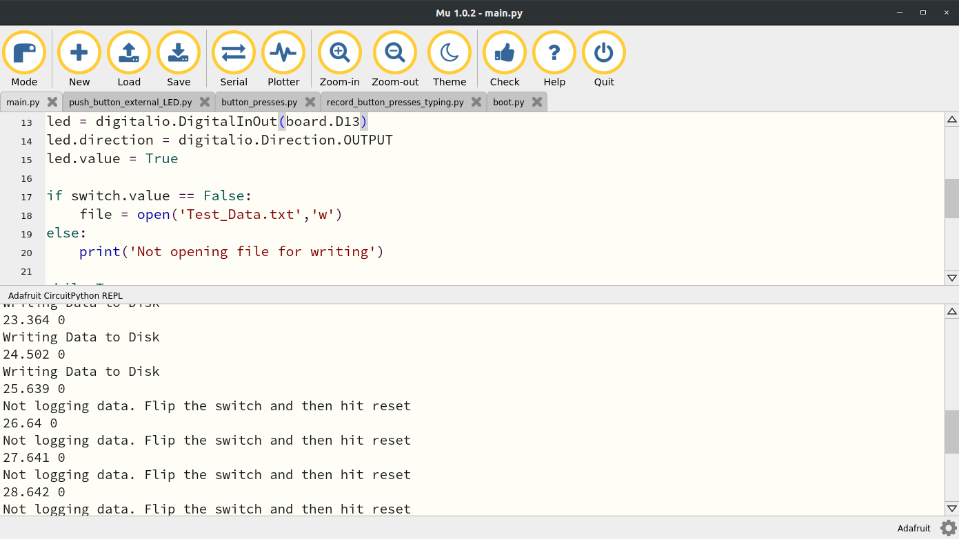
When you are done taking data simply slide the switch over towards the A button and hit reset again. This is what my Serial monitor looks like when I do this. You’ll see that I was writing to disk for like 25 seconds and then I flipped the switch back towards the A button.
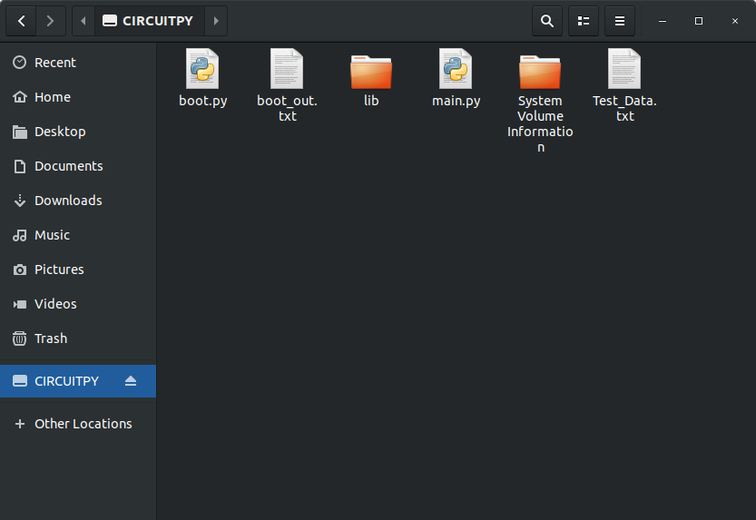
With the switch flipped and data taken, open your folder manager and take a look at the CIRCUITPY drive. This is what mine looks like. You’ll see I have two CircuitPython files and a file Test_Data.txt with all my data in it.
If you open the Test_Data.txt file you will hopefully see data in it.
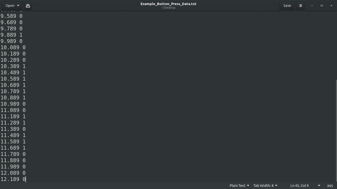
At this point you can copy this text file over to your desktop computer and proceed to the plotting portion. Ok so let’s recap method 3 one more time.
-
Unplug CPX (or remove power)
-
Slide switch to A
-
Plug in CPX (or provide battery power) and wait for system to fully boot up
-
Slide switch to B
-
Hit Reset and wait for system to fully boot up
-
Take data for however long you want
-
Slide switch to A when you’re ready to stop taking data
-
Hit Reset and wait for system to fully boot up
-
Remove power if you’re on battery power
-
Plug CPX into computer if not already connected
-
Transfer data file to computer
