Section 24.2 CPB Wiring and Software
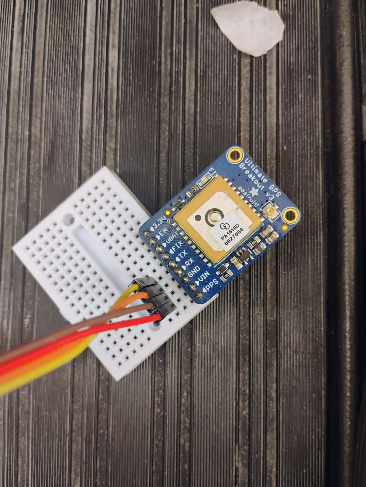
The only difference between the wiring diagram shown previously and the CPX/CPB is that you will be using 4 alligator clips. The rest is straightforward. You need 3.3V to run to VIN, GND to GND and then TX to RX and RX to TX. That is the TX and RX pins are swapped so that the transmit wire goes to the receive wire on the other device.
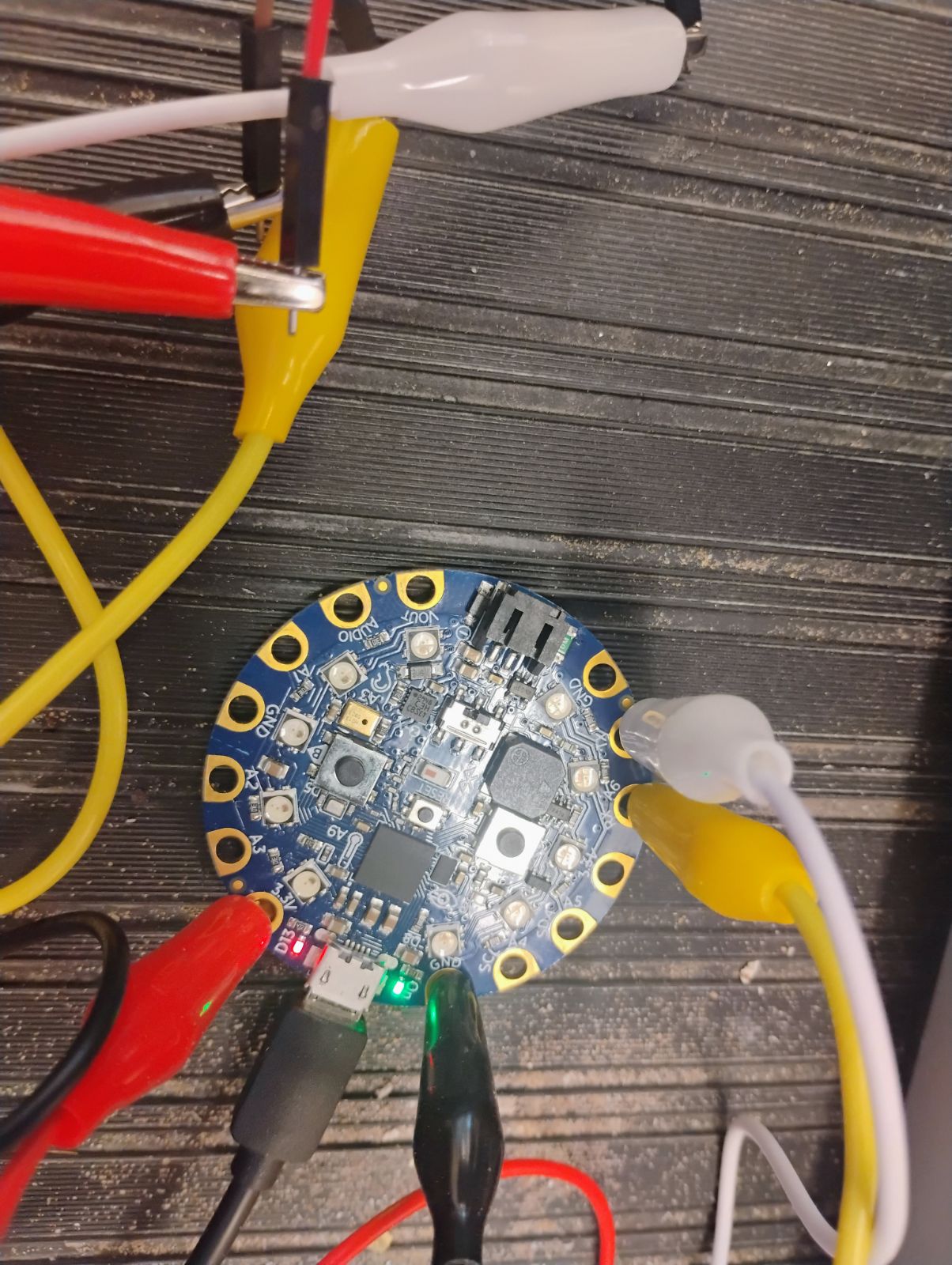
In the photos above and below, the red alligator clip is connected to 3.3V and is then connected to a red male-male wire which is then connected to the VIN pin on the GPS. The black alligator clip is connected to the GND pin which is connected to a brown male-male wire connected to the GND pin on the GPS. The white alligator clip is connected to the TX pin connected to an orange male-male wire connected to the RX pin on the GPS. Finally, the yellow alligator clip is connected to the RX pin connected to a yellow male-male wire connected to the TX pin on the GPS.
Once you have the circuit wired and soldered it’s time to work on software. First, you want to make sure you have your Circuit Python UF2 up to date[30]. Once I updated my UF2 I also updated my Circuit Python Libraries (See Section 7.2 for help on installing extra modules on your CPX/CPB)[30]. In this lab I purposefully made the code a bit more elaborate by adding, bluetooth, and method 3 data logging. The reason is that my students in Flight Dynamics and Aircraft Design have to build a hobbyist radio controlled aircraft and get GPS data during the flight. This way they know where they flew and how fast. As such they need to build a standalone datalogger that can be placed into an airplane. The specific modules I needed for this lab for all of that functionality is as follows:
-
adafruit_lis3dh
-
adafruit_gps
-
adafruit_thermistor
-
neopixel
-
adafruit_ble
Notice that I also added the thermistor and lis3dh libraries to get acceleration and temperature from the CPB. Once you have the necessary modules you can run some example code. Once you have all the modules, you can run the example code to log gps and acceleration data. Note that the link previously shown is to a folder of a few different pieces of software. The reason is because some students have a CPX that doesn’t have bluetooth. Make sure to select the correct version for your hardware. Once you get it working the output will look something like this.
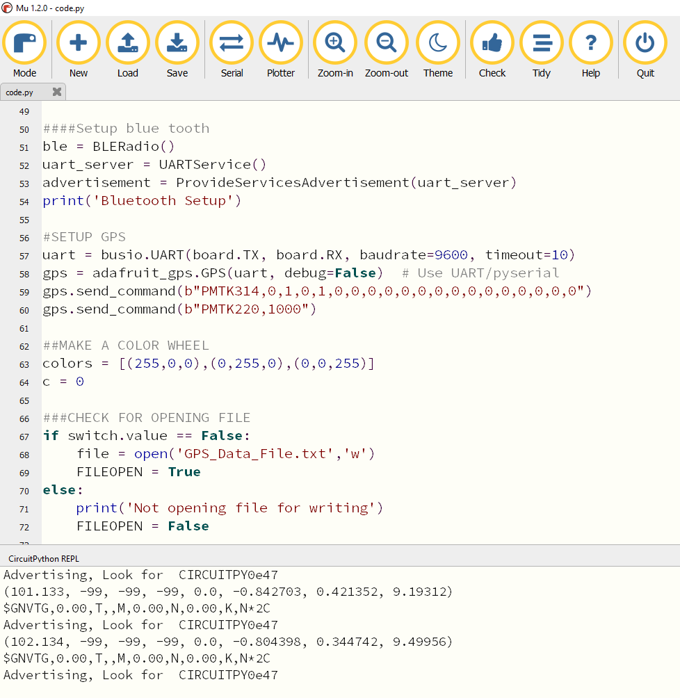
Notice that in the photo above the multiple columns of data are time,-99,-99,-99,0.0,x accel,y accel, z accel. The -99 values are dummy values for latitude, longitude and altitude because the GPS doesn’t have a lock on any satellites. The 0.0 is the speed in knots which is also zero because there is no lock. The x,y,z accel values are from the accelerometer on the CPB. Move to Section 24.4 to learn about getting a lock and how to process the GPS information once you get a lock.
