Although a CPX has numerous sensors built in, you can easily augment the capabilities of the CPX using either I2C or just the ADC on board the CPX. In this lab, if you purchased a pitot probe you will be able to do this assignment[40]. Since you don’t need the pitot probe for very long you can always borrow one from some other team or from your instructor if they have one. Let’s talk about the hardware and the wiring to get this to work. First, pitot probes work by mechanically changing the dynamic pressure of the incoming airflow as shown in the figure below (Courtesy of Joshua Hrisko) [39].
The pitot probe has two pressure taps that measure static (ambient) pressure and dynamic (stagnation) pressure. These taps move through two silicon tubes to a pressure transducer that has a strain gauge that separates both pressures. When the pressure on one side of the transducer is larger than the other, it will flex the membrane and create strain. This strain runs through a wheatstone bridge with a voltage offset to the pin labeled analog. The analog signal from the analog pin will be denoted as \(V_{pitot}\text{.}\) The pressure transducer used in this lab is the MPXV7002 which is a differential pressure sensor. The datasheet indicates that the voltage offset of the pitot probe is 2.5V and the change in voltage is proportional to the change in pressure in units of kPa[41]. This means that \(\Delta P\) is given by the equation below.
remembering that \(V_{pitot}=3.3D_o/65535\text{.}\) Also note that 2.5V is the nominal voltage even though your sensor might have something slightly different like 2.4V or 2.6V. To measure wind speed you can use a variation of Bernoulli’s principle. Note it is necessary to convert the pressure \(P\) from kilopascals (kPa) to Pascals (Pa) by multiplying by \(1000\) before using it in this formula.
\begin{equation}
U = \sqrt{\frac{2 \Delta P_{Pa}}{\rho}}\tag{14.0.2}
\end{equation}
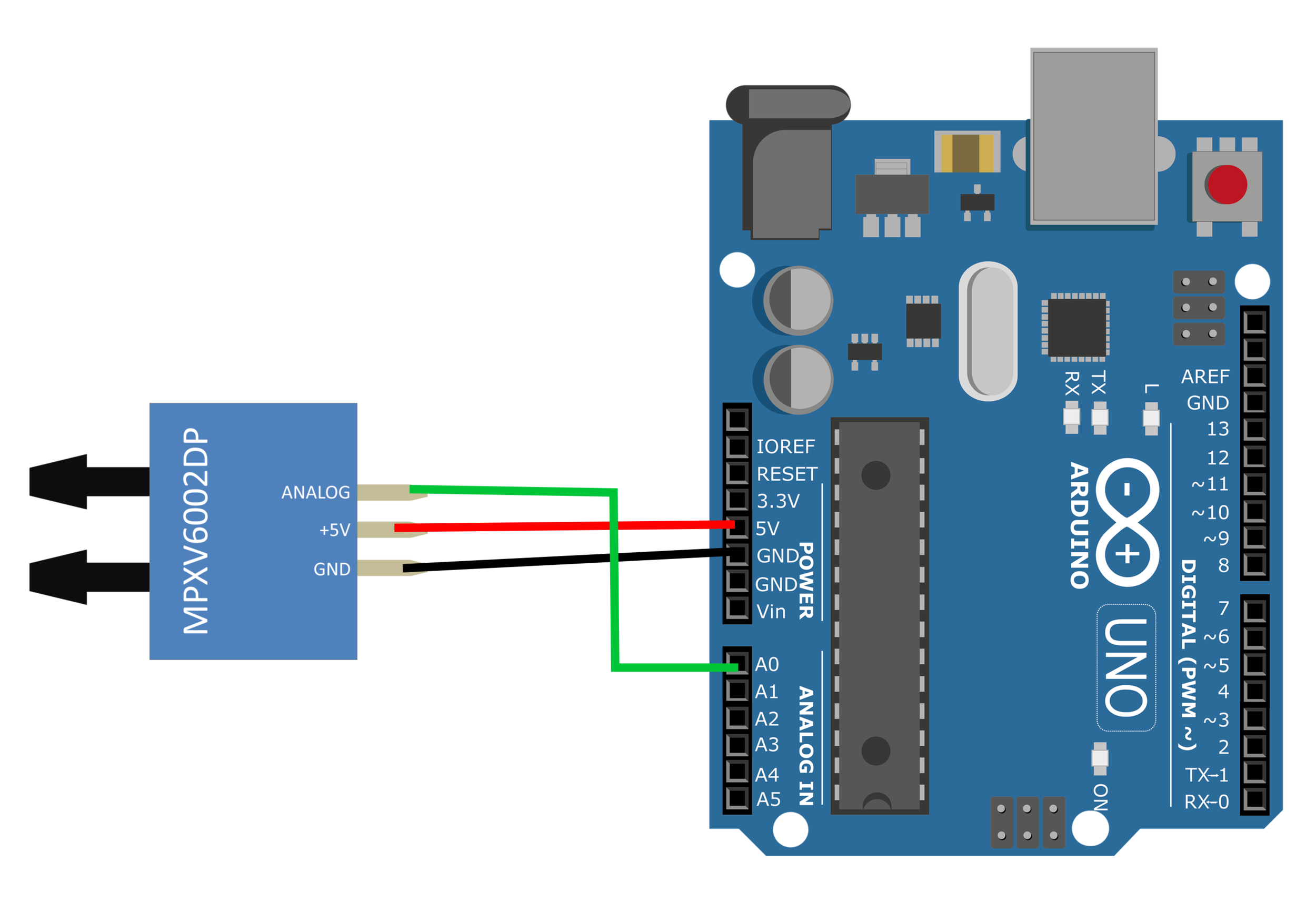
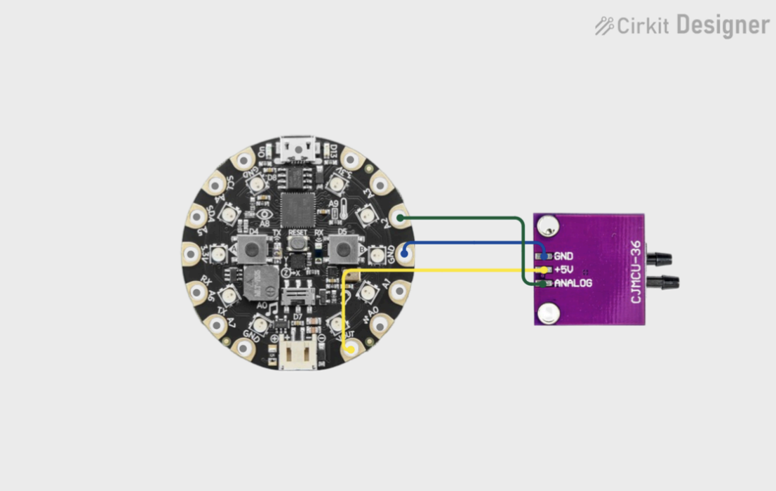
where \(U\) is the wind speed in \(m/s\text{,}\)\(\Delta P\) is the differential pressure (in Pascals), and \(\rho=1.225~kg/m^3\) is the density of air. As for wiring up the circuit itself, the transducer has 3 pins, +5V, GND and Analog. The figure below shows the transducer connected to an Arduino (Courtesy of Joshua Hrisko)[39].
Figure14.0.4.Arduino connected to a pressure transducer[39]
Remember that +5V needs to go to VOUT, GND to GND and Analog to any analog pin. Continue to read on to setup your own CPX/CPB and complete this assignment