Section 24.1 GPS Setup
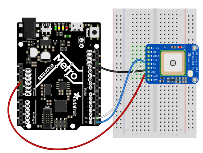
When you open the packaging of this breakout board you’ll notice that the header pins are missing. First you’ll need to cut a row of 9 pins and solder the header pins to the sensor. If you’re taking my class I can solder this for you or teach everyone about soldering during a lecture session of class. If you are taking this class elsewhere you have two options: try and find someone who can solder this real quick (only takes about 5 minutes) or buy your own soldering iron and try to solder yourself. Once the device is soldered you can "plug" it into a breadboard. The wiring for this system requires 4 wires. The figure below shows the GPS sensor connected to an Adafruit Metro M0. (Courtesy of Lady Ada herself!)[32].