In order to prepare for this lab, be sure you are familiar with photocells and how they work (See Subsection 15.1.1). The only difference between Subsection 15.1.1 and this lab is that you’re going to use an external photocell which means you need to build your own voltage divider circuit. Once you have the photocell wired up to the CPX/CPB you can use the same code as the potentiometer lab to take data and then plot that data on your desktop computer. The second part of this lab is to take 1000 data points at three different light levels and create a histogram of the data as well as compute the mean, median, and standard deviation of the data. Finally, you are going to superimpose a Gaussian distribution on top of your histogram to see how close your data is to a normal distribution. This will be a good exercise in understanding the noise in your system and how that noise is distributed.
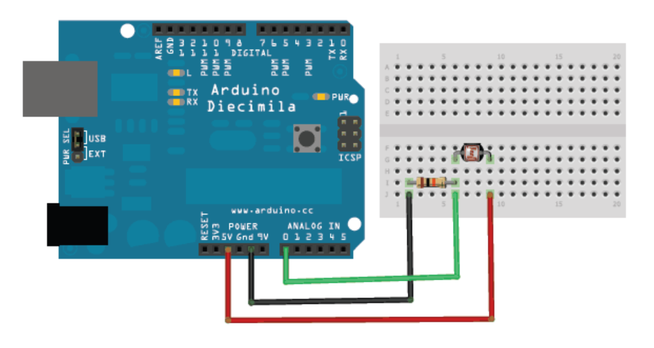
Wiring a photocell is similar to a potentiometer (See Chapter 13) and remember that you need a resistor in series with the photocell to create the voltage divider circuit. The photo below also shows a voltage divider circuit of a photocell using an Arduino (Courtesy of Lady Ada herself!)[32].
Figure18.0.3.Photocell wired up to an Arduino[44]Note that any \(\Omega\) value will do for the resistor.
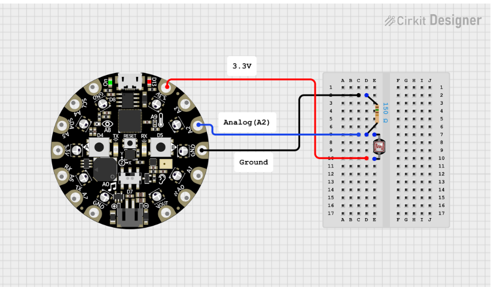
Wiring this circuit to a CPX is almost identical to the Arduino. The only difference is that you need to use alligator clips instead of using jumper wires and a breadboard. You also need to use 3.3V instead of 5V since the CPX is running on 3.3V logic.The wiring diagram is shown below. Again, the diagram below shows a 150 \(\Omega\) resistor but you can use any value you like.
Figure18.0.4.Wiring diagram for photocell circuit on CPX
Note that in this case the resistor is before the photocell but it doesn’t matter which way you wire it as long as the resistor and photocell are in series and you measure the voltage across the photocell. If you end up measuring the voltage across the resistor as is shown in the figure above, the voltage divider equations will change and thus effect your light level measurement. Notice the difference in equations below depending on where you measure the voltage.