Section 11.1 Setting up the CPX/CPB
Before wiring up the system I recommend setting up the CPX/CPB first before wiring up the system. The example code we’re going to use for this chapter is on Github as usual.
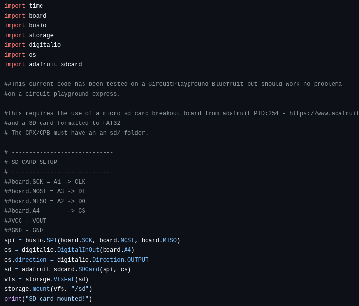
The figure above shows the preamble of the code which has a few things that you need to do before getting this to work. First, you need to have an sd folder in the your CIRCUITPY drive. That means, when you plug in the CPB/CPX to your computer you must add a solder called sd into the main folder alongside the lib folder which needs the adafruit_sdcard module. Before installing extra modules into the lib folder you want to make sure you have your Circuit Python UF2 up to date[30]. In this example I’m using the 10.X version. Once I updated my UF2 I also updated my Circuit Python Libraries (See Section 7.2 for help on installing extra modules on your CPX/CPB)[30]. Again, for this lab you just need the adafruit_sdcard module in the lib folder. After that you can copy the software from Github into your code.py file and save it. The code will not run right away and will probably through an SD Card Not Found error. At this point you can unplug the CPX/CPB and begin wiring the breakout board making to plug in the micro SD card of course.
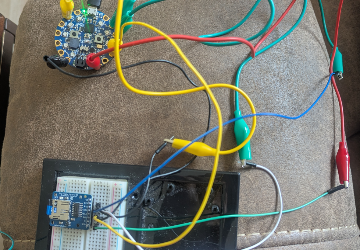
In the figure above moving counter-clockwise, the red alligator clip from 5V to a green male-male wire to 5V, the first yellow alligator clip goes directly from A1(CLK) to CLK, the first green alligator clip goes from A2(MISO) to a white male-male wire to DO, the second green alligator clip goes from A3(MOSI) to a blue male-male wire to DI, the second yellow alligator clip is connected to A4 then to a black male-male wire connected to CS and finally the black alligator clip goes directly from GND to GND.
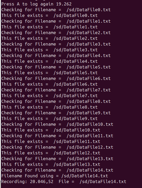
Once you plug in the CPB/CPX and press the A button to start recording you can press the A button over and over again to stop logging and then restart logging. Everytime you close the file and open a new file, the code will find a new file to create so that you don’t continue to overwrite the file that is already on the sd card. In this code the A button is used to start and stop recording and the B button along with a dummy counter is logged to the SD card.
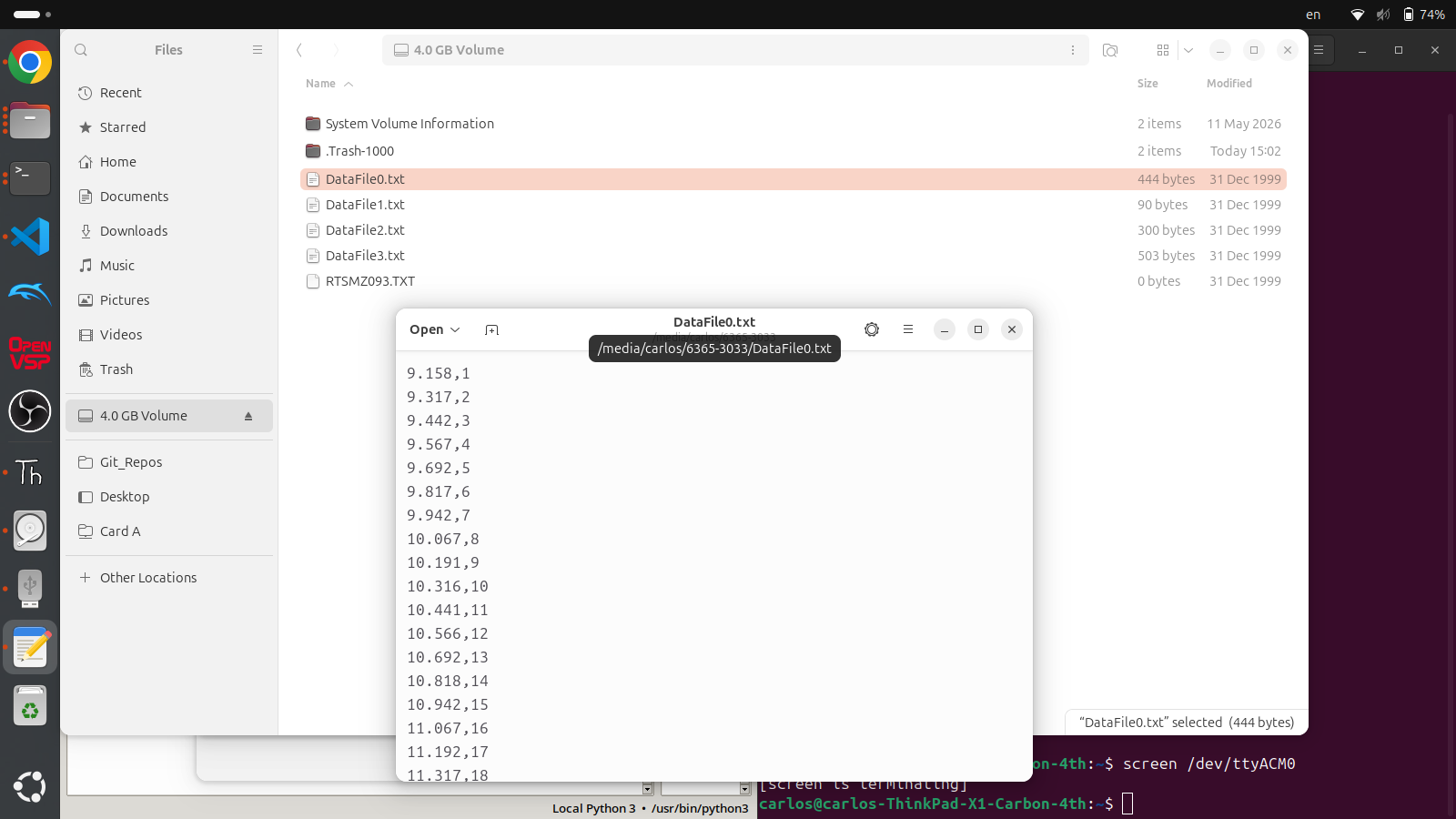
When you are done recording make sure to press the A button to the close the current file and then remove power from the CPX/CPB. You can then place the SD card into your computer and you should see multiple DataFile#.txt text files in your computer. You can then copy those to your computer and plot the data similar to Chapter 9. This code can easily be augmented to accommodate any other sensor such as GPS (Chapter 24), accelerometer (Chapter 22), pressure (Chapter 23) or any other sensor you can think of. Although you add the complexity of having an extra piece of hardware, you remove the software headache and potential bricking of your CPX/CPB by attempting to use Method 3 (Chapter 9) while still removing the need for a laptop.
