Section 8.1 LED with no Code
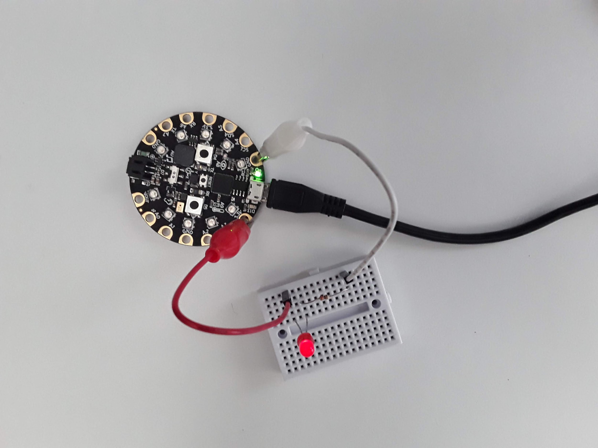
For this part we are going to light up the LED without the use of any code on the CPX. First, wire up the circuit with the positive end connected to 5V. This is how my circuit looks. Make sure to use a resistor between 150 and 1000 \(\Omega\text{.}\) An LED does not have that much internal resistance so you need a resistor in series with an LED to reduce the amount of current flowing through the LED or the entire LED will fry. If you use a resistor that has too much impedance the LED just won’t turn on because the voltage/current through the LED will be below the activation voltage of the circuit.
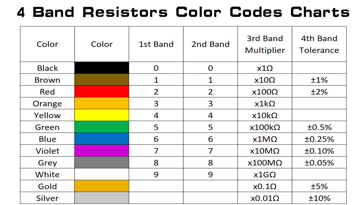
One issue that you may run into is not knowing which resistor is which. It’s actually possible to ascertain the resistance in the resistor by looking at the color bands of the resistor. It’s definitely not something worth memorizing but many color charts exist online for you to look at. I’ve included one below for your convenience. The first two bands are the first two digits of the resistance value, the third band is the multiplier and the fourth band is the tolerance. For example, if you have a resistor with color bands of red, violet, brown and gold, that would be 2 (red), 7 (violet) and 10 (brown) which is 270 \(\Omega\) with a tolerance of 5% (gold). If you have a resistor with color bands of brown, black, red and gold, that would be 1 (brown), 0 (black) and 100 (red) which is 1000 \(\Omega\) with a tolerance of 5% (gold). Note that if you have a 5 band resistor, the first three bands are the first three digits of the resistance value, the fourth band is the multiplier and the fifth band is the tolerance.
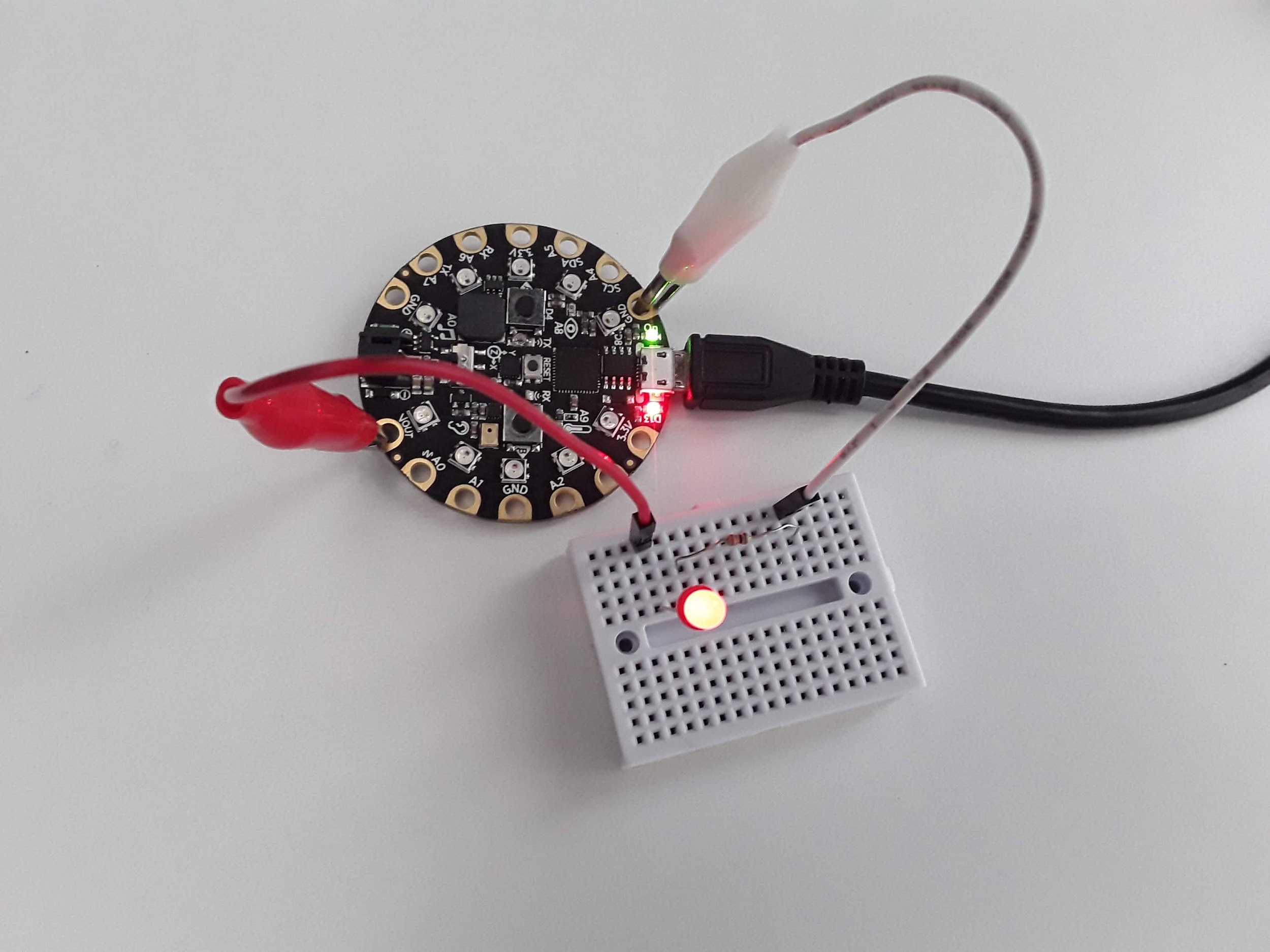
Once you have that circuit working, wire up the circuit again with the 3.3V output. Do you notice anything different when you hook up the circuit with different pins? Here’s my circuit. Do you notice something different about the intensity of the LED? Why is it different?