Section 24.3 Arduino Wiring and Software
The wiring for the Arduino depends on which type of Arduino you’re using. For every Arduino the Serial0 pins are hardwired to the USB port so you can’t use them which means you need to use Serial1 or similar. The problem is that the Arduino UNO does not have any more serial ports so you have to use SoftwareSerial. When using SoftwareSerial you can plug the TX/RX pins into any two digital ports and then create a SoftwareSerial instance. If you’re using an Arduino MEGA you can use any of the hardware Serial ports. In the figure below the GPS is plugged into Serial1 and thus TX on the GPS is connected to RX1 on the Arduino MEGA and RX on the GPS is connected to TX1 on the Arduino MEGA. The Figure below also has an IMU (Chapter 22) and micro sd card breakout board (Chapter 11) connected to the Arduino to build a standalone datalogger capable of measuring acceleration and GPS and log that to a micro SD card.
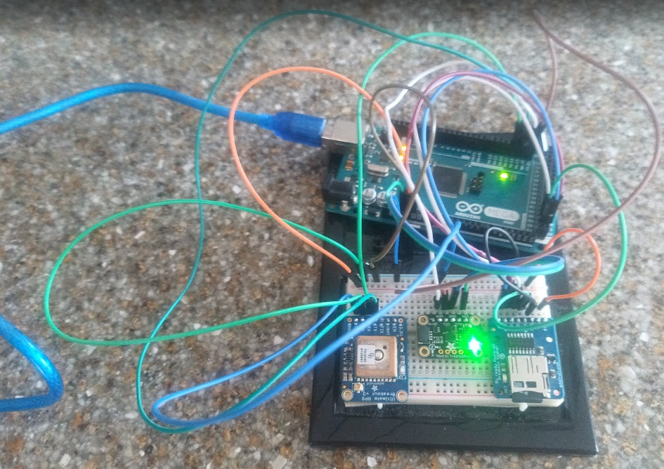
In the Figure above, the blue wire goes from VIN to 5V on the Arduino, the left most green wire goes from GND to GND while the next two green wires connect TX/RX to RX1/TX1 respectively on the Arduino MEGA. Moving on to software also depends on the Arduino MEGA or UNO. On the UNO since you’re using SoftwareSerial you need to ensure that you have #include <SoftwareSerial.h> at the top of your code and that the SoftwareSerial library is installed in Arduino IDE. Thankfully SoftwareSerial is already built-in to the Arduino IDE so there’s no need to download it. The code for an Arduino UNO example can be found on Github but will not be shown in this chapter. Notice though that on line 33 upon following that link, pins 8 and 7 are used for the SoftwareSerial port given by this line of code: SoftwareSerial mySerial(8, 7);. For the Arduino MEGA, the code is also on Github but the Serial port is different as shown in the code below.
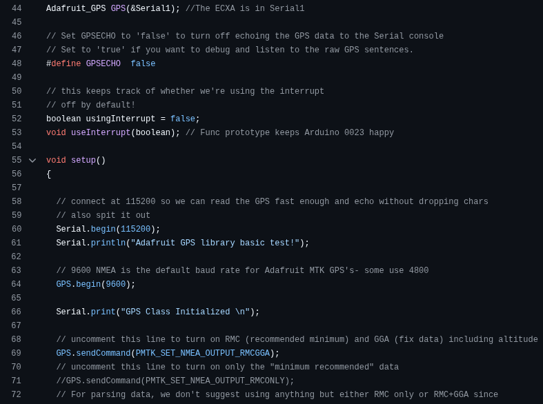
Notice, in this code the call to create the GPS object is done using &Serial1 rather than &mySerial which is an instance of the SoftwareSerial library. While &Serial1 is simply built-in to the Arduino MEGA software suite &mySerial is a specific instance of SoftwareSerial that is only required on the Arduino UNO or similar boards that don’t have Hardware Serial capabilities. However, for either the Arduino UNO or MEGA it is still required to get the Adafruit_GPS library which can be downloaded from Github and installed by navigating to Sketch>Include Library>Add .ZIP Library... and then add the ZIP file you just downloaded. This library is needed to parse the specific raw GPS sentences (Section 24.4) coming in. Once you’ve installed all the libraries, compiled the code, wired up the Arduino with the GPS and flashed the code you should be able to open the Serial Monitor with a baud rate of 115200 and see the GPS output.
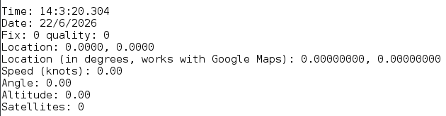
The Figure above shows the GPS output when you don’t have a lock on any satellites which is why Latitude and Longitude have zeros. Still, this is a good check to make sure you’re getting information correctly from the GPS since the date and time is typically accurate even without a lock. Move to Section 24.4 to learn about getting a lock and how to process the GPS information once you get a lock. Along with getting a lock on the GPS, it’s possible to augment the software to also read the external IMU from I2C and log all data to the micro SD card. A snippet of the software is shown below while the software itself for a standalone GPS+IMU datalogger is on Github us usual.
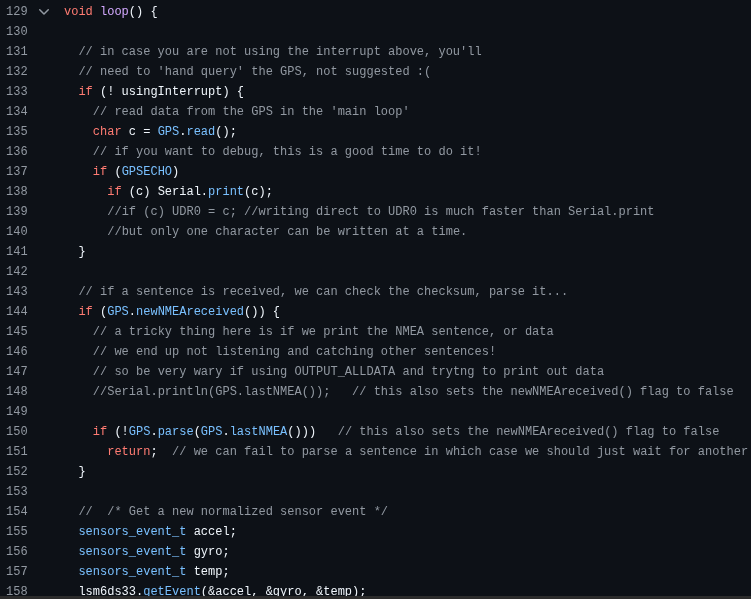
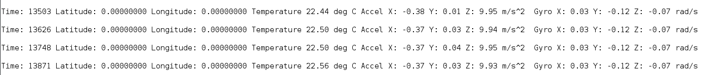
The code shows the loop routine polling the GPS using the useInterrupt function as well as the sensors.getEvent() routine to poll the IMU. After compiling the code, verifying the hardware connections and flashing the software the Serial monitor will produce something similar to the code below. Again in this case the latitude and longitude are shown as zeros because there is no lock.