Section 25.1 Load Cell Setup
When you open the packaging of the amplifier and strain gauge, you’ll notice that the header pins on the amplifier are missing. First you’ll need to cut a row of 6 pins and solder the header pins to the sensor. If you’re taking my class I can solder this for you or teach everyone about soldering during a lecture session of class. If you are taking this class elsewhere you have two options: try and find someone who can solder this real quick (only takes about 5 minutes) or buy your own soldering iron and try to solder yourself. Once the device is soldered you can "plug" it into a breadboard. The wiring for this system requires 4 wires from the microcontroller to the amplifier and then 4 wires from the strain gauge to the amplifier. The figure below shows the load cell and load cell amplifier connected to a Feather M4. (Courtesy of Liz Clark)[32].
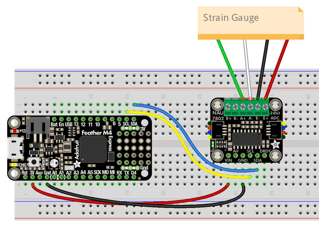
In the wiring diagram above, the strain gauge is connected to the amplifier with 4 wires. The red wire is connected to E+, the black wire is connected to E-, the white wire is connected to A- and the green wire is connected to A+.
