Chapter 22 Inertial Measurement Unit
In this lab we’re going to use an Inertial Measurement Unit (IMU) sensor to measure angular velocity and the magnetic field of the surrounding environment.
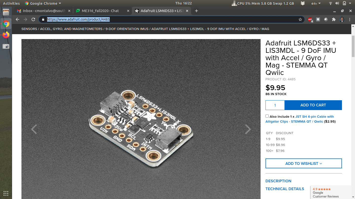
The sensor above is the LSM6DS33+LIS3MDL[34]. You basically have 2 separate microchips in one. The first (LSM6DS33) is a 3-axis accelerometer and 3-axis rate gyro. The first measures acceleration and the second measures angular velocity. The LIS3MDL is a 3-axis magnetometer which measures magnetic fields. The three of these sensors put together (accelerometer, rate gyro, magnetometer) is called an IMU (Inertial Measurement Unit). It’s actually possible to measure roll and pitch of an airplane using the accelerometer and heading using the magnetometer. Combining the angular velocity of the rate gyro can create a complete attitude estimation algorithm for six-degree-of-freedom vehicles (6DOF). This sensor does not come standard in the current iteration of the kit but you can purchase one on Adafruit for only $10 at the time of this writing. The interesting thing about this device is that you can actually purchase the LSM6DS33 and LIS3MDL separately but this breakout board has both chips on board. The goal of this lab is not only to use this specific sensor but to understand IMUs and I2C protocol.Most if not all breakout boards on the Adafruit website use I2C communication. You’ll know if the breakout board uses I2C if you find SDA/SCL pins on the board. It will also say it in the quick description of the sensor.
The nice thing about this sensor is that there is a magnetometer on board. Recall that the accelerometer can be used to measure roll and pitch (See Subsection 15.1.4). By combining the magnetometer in this IMU, it’s possible to get the compass heading of the sensor.
\begin{equation}
\psi = tan^{-1}\left(\frac{\bar{\beta}_z s_{\phi} - \bar{\beta}_y c_{\phi}}{\bar{\beta}_x c_{\phi} + \bar{\beta}_y s_{\theta}s_{\phi} + \bar{\beta}_z c_{\phi}s_{\theta}}\right)\tag{22.0.1}
\end{equation}
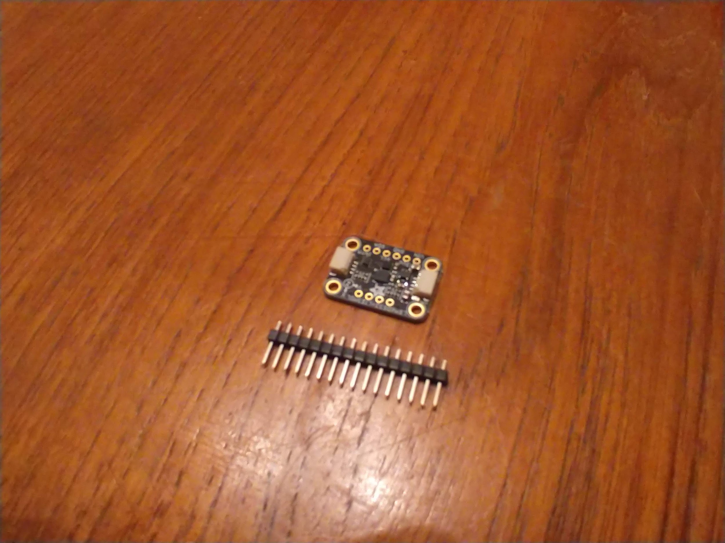
In the equations above, \(\beta\) is the magnetic field along all 3 axes. Again shorthand is used for cosine and sine functions and the derivation is left for another course entirely (See Aerospace Mechanics)[33]. When you open the packaging of this breakout board you’ll notice that the header pins are missing. First you’ll need to cut a row of 4 and 6 for the top and bottom side of the board and solder the header pins to the sensor. If you’re taking my class I can solder this for you or teach everyone about soldering during a lecture session of class. If you are taking this class elsewhere you have two options: try and find someone who can solder this real quick (only takes about 5 minutes) or buy your own soldering iron and try to solder yourself. Once the device is soldered you can "plug" it into a breadboard.
