Chapter 19 Servo Control
-
Understand what a PWM signal is and how it affects a servo
-
Understand the inner workings of a servo and how to make it move
-
Practice first order regression and calibration techniques
-
Understand how to compute roll and pitch from an accelerometer
-
Learn the fundamental concepts of feedback control
-
Learn how to Combine two codes (servo code and accelerometer code into one)
For this lab we are going to learn how to drive a servo[34]. Servos accept what are called Pulse-Width-Modulation(PWM) signals which are basically square waves of varying frequency. The servo itself has a microprocessor on board that turns a DC motor based on the incoming PWM frequency which is typically called a duty cycle. The DC motor runs through some gears to rotate a shaft. Because of this rotation, you can make a number of things move! Servos are used for all sorts of things, opening doors, deflecting control surfaces on RC aircraft and many more. The neat thing about PWM signals is that they can not only move servos but they can also drive electronic speed controllers (ESCs) to turn 3 phase motors and even change the light intensity of LEDs. Servos typically come in two different color schemes as shown below.
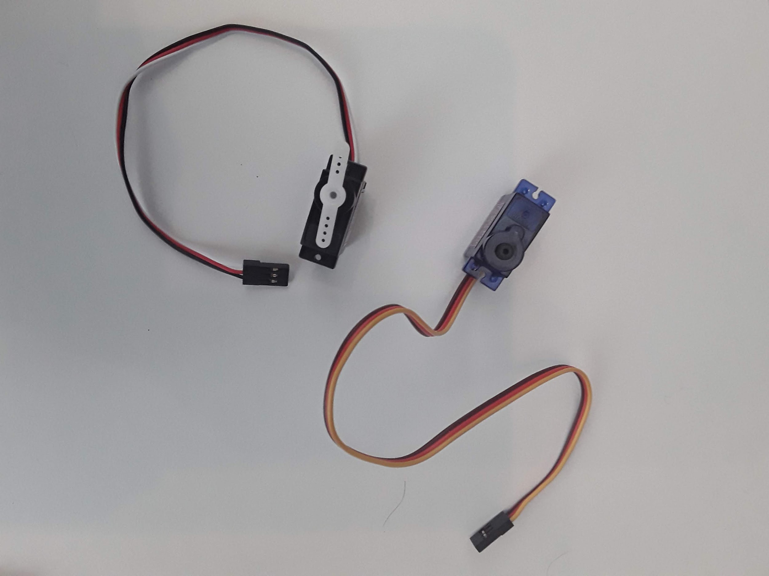
The servo on the right is a micro servo and the one on the left is a standard servo. The micro servo is smaller and typically has less torque than the standard servo. For this lab you can use either one but I recommend using the micro servo since it draws less current and thus is less likely to cause your CPX to brown out. If you have a standard servo you may want to consider powering it with an external power supply instead of the CPX. The wiring for both servos is the same so it doesn’t matter which one you use.
For this lab we are going to first learn how to change the PWM frequency on the CPX/CPB and turn the servo. Then we are going to experimentally find the limits of the servo and create a calibration curve to relate servo angle (deg) to PWM signal (ms). Finally, we are going to use the accelerometer on the CPX/CPB to measure pitch and roll (See Subsection 15.1.4) and use that information to feedback to the servo. This is a very common control problem in aerospace engineering and is a great example of how to combine different pieces of code together to create a more complex piece of software.
As can be easily seen when you look at the servo, servos have 3 pins (GND, PWR, SIGNAL). A wiring diagram of a servo connected to the CPX/CPB is shown below (Couresy of Kattni Rembor)[32].
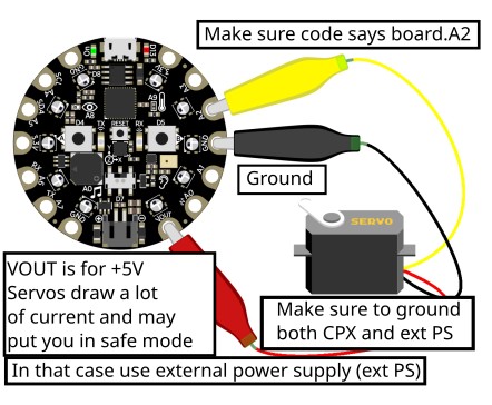
The brown or black wire is GND, the red wire needs to go to a 5V signal so for the CPX it needs to go to the VOUT pin and the yellow or white wire is the signal wire which need to go to an analog port on the CPX that supports PWM signals. Which ones support PWM signals? Adafruit Learn has a great description of which pins support PWM signals but as a quick check you can use the following analog pins: A1, A2, A3, A6 and A7.[32].
